Rebody Pingu's Kit Car Project

Pingu

Zorg Guru (III)
3rd Party Trader
Joined
Dec 8, 2011
Points
145
I've just seen something that is quite a problem. It has probably been caused by the body flexing due to sleeping policemen and potholes, both of which I negotiate slowly.

Roof cracking...

IMG_20240514_171404.jpg


IMG_20240514_171418.jpg


IMG_20240514_171435.jpg


IMG_20240514_171505.jpg


The joys of fibreglass 🤪 .

Any recommendations for the best flexible filler paste?
 

Duncodin

Zorg Guru (III)
Supporter
Joined
Sep 8, 2021
Points
139
Location
Pontrhydyrun
Model of Z
Z3 M44
Kinda looks like there's a metal screw head or rivet or something like that just under the surface.
 

Pond

Zorg Guru (III)
British Zeds
Joined
Dec 26, 2016
Points
144
Location
Spaldingski, Lincs
Model of Z
Z3 project and E89 Z4
That is awful! :eek:
How the hell did that happen?

It is posts like this that convince me building kit cars is not really my thing! :mad:
 

Pingu

Zorg Guru (III)
3rd Party Trader
Joined
Dec 8, 2011
Points
145
That is awful! :eek:
How the hell did that happen?

It is posts like this that convince me building kit cars is not really my thing! :mad:
Car bodies flex. GRP doesn't.

There is a foam or wooden batten between the roof and the top of the windscreen. It has been attacthed to the roof with screws that were covered with filler as well as TigerSeal. It may not have happened if had just been TigerSeal, but the seal may not have been tight enough.

Re the failure. The fibres can flex, but the gel can't. The immediate problem is contamination getting into the structure, and crack propagation. The bond between the fibres and the gel doesn't like anything getting in there. It's like rust once that starts.

The cracks can be stopped by drilling a hole at the end of them. One of them has hit the edge already, the others need to be stopped before they head towards the centre of the roof.
 

IainP

Zorg Guru (II)
British Zeds
Joined
Feb 20, 2019
Points
119
Location
Out of my Tree, North of Perth, Scotland
Model of Z
1.9
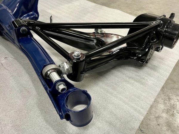
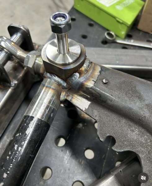
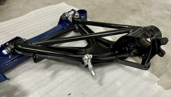
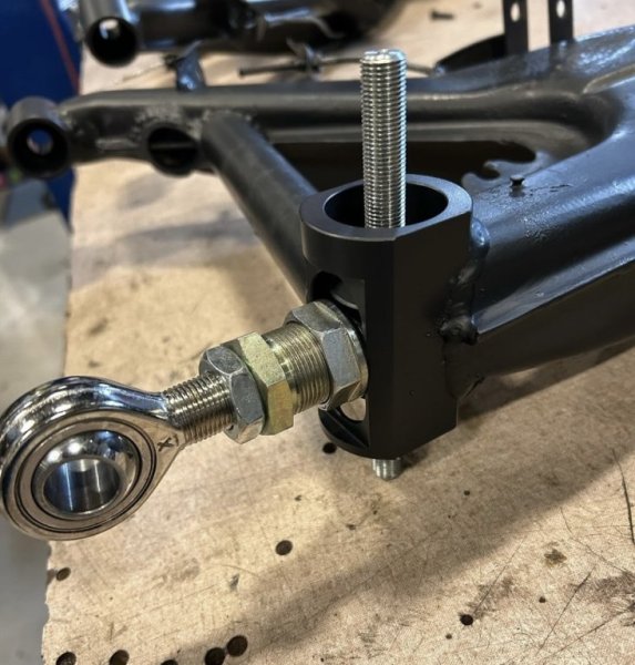
“The rear beam has been done...”

After your post I went down a rabbit hole researching reinforcements for e30 rear beams. They are out there, but it’s usually just plates at the two mounting barrels and curved sections to brace the diff.
Some of the bracing and adjustment to the arms is seriously spectacular, though a lot of those cars are running upwards of 450hp.
IMG_5823.jpegIMG_5819.jpegIMG_5825.jpegIMG_5818.jpeg
 

Pingu

Zorg Guru (III)
3rd Party Trader
Joined
Dec 8, 2011
Points
145
“The rear beam has been done...”

After your post I went down a rabbit hole researching reinforcements for e30 rear beams. They are out there, but it’s usually just plates at the two mounting barrels and curved sections to brace the diff.
Some of the bracing and adjustment to the arms is seriously spectacular, though a lot of those cars are running upwards of 450hp.
View attachment 301879View attachment 301881View attachment 301883View attachment 301885
As @deano1712 says, anyone can make it stronger by chucking more metal at it =))
 

Pingu

Zorg Guru (III)
3rd Party Trader
Joined
Dec 8, 2011
Points
145
I had a problem with the previous "Parking Light Module", so I've made one that is more robust...

The module on the left is the switch. The module on the right is the parking light module. It takes the place of the Z3 light switch. There are diodes (not all shown) on each of the wires both coming into and leaving the module.

IMG_20240526_223549_816_408.jpg


Diagram of what the circuit board needs to look like...

IMG_20240526_223609_816_408.jpg


IMG_20240525_184531_816_408.jpg


IMG_20240525_184518_816_408.jpg


I used some fibreglass resin to seal the electronics...

IMG_20240526_165330_816_408.jpg


IMG_20240526_223447_816_408.jpg
 

Pond

Zorg Guru (III)
British Zeds
Joined
Dec 26, 2016
Points
144
Location
Spaldingski, Lincs
Model of Z
Z3 project and E89 Z4
That is a very neat wiring diagram......can you now explain why it may be needed please?
 

Pingu

Zorg Guru (III)
3rd Party Trader
Joined
Dec 8, 2011
Points
145
That is a very neat wiring diagram......can you now explain why it may be needed please?
It's what is needed if you want to replace the original Z3 light switch with an "off, side and side+head" switch (0, 1, 1+2) .

The Z3 switch is quite a complicated switch. It controls five outputs with three inputs (six outputs with four inputs if you have front foglights).

And I've not included a dimmer in the circuit 🤪
 
Last edited:

Pond

Zorg Guru (III)
British Zeds
Joined
Dec 26, 2016
Points
144
Location
Spaldingski, Lincs
Model of Z
Z3 project and E89 Z4
It's what is needed if you want to replace the original Z3 light switch with an "off, side and side+head" switch (0, 1, 1+2) .

The Z3 switch is quite a complicated switch. It controls five outputs with three inputs (six outputs with four inputs if you have front foglights).

And I've not included a dimmer in the circuit 🤪
Thanks
I shall keep the Z3 one then. I actually connected all my new lights up last night, just to check my extended wiring and make sure the car 'liked' the new lights. All good.
 

deano1712

Zorg Legend
Joined
Jan 2, 2012
Points
74
Location
Leeds
Model of Z
Z3M
A little more than a ‘wee run’. I was pretty pleased with my new driveshaft.

As far as e-jot points I have it won for substandard fault diagnosis.
 
Top